Light Instead Of Copper
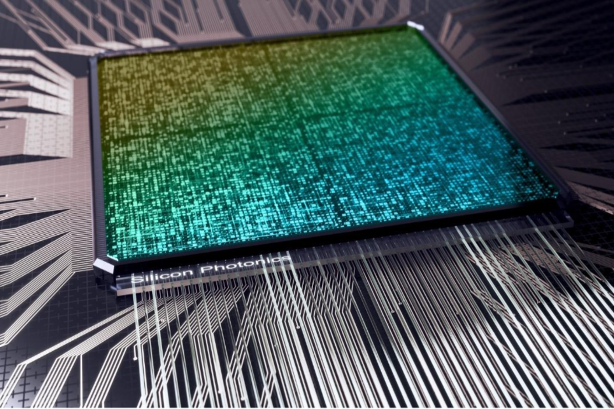
Silicon photonics moves data by encoding electrical signals onto light, then guiding that light through microscopic optical waveguides on a silicon chip. Copper traces carry electrons; optical links carry photons. The key advantage shows up when you need high bandwidth over short to medium distances without the same electrical losses and crosstalk that copper faces.
In a typical architecture, an electrical serializer drives a modulator that changes a property of light—often intensity or phase—at the data rate. A photodetector converts the modulated light back into an electrical signal at the receiver. The “silicon” part matters because silicon photonics uses fabrication steps compatible with semiconductor manufacturing, so optical components like waveguides, splitters, and couplers can be patterned with high repeatability.
Practical examples include data-center interconnects where links run at tens to hundreds of gigabits per second per lane, and telecom systems where optical transport spans longer distances. Even when the overall system still uses electrical switching at servers, the optical segment reduces the burden on long copper runs. I first saw this described clearly in a 2019-era lab note where the optical link budget was treated like a budget for power and noise, not just “speed,” which helped me separate marketing from physics.
Main Problems People Miss
People often assume “light equals faster,” then ignore the bottlenecks that decide whether a link actually works. A photonic link has multiple constraints: modulator bandwidth, laser linewidth and stability, optical signal-to-noise ratio, receiver sensitivity, and dispersion effects in the fiber or waveguide. When any one of those limits is hit, the system may cap out at a lower data rate or require heavier forward error correction.
Another common mistake is treating silicon photonics as a single component. In practice, it is a system of parts: a light source (often a laser outside the chip or integrated in some designs), a modulator on silicon, optical coupling between chip and fiber, and a detector plus transimpedance amplifier at the receiver. Coupling losses at interfaces can dominate the link budget, and those losses depend on alignment, packaging, and surface quality—details that rarely fit on a slide.
Supporting technologies also shape performance. High-speed electronics determine how clean the electrical drive is, and digital signal processing determines how much impairment can be corrected. For example, many optical receivers use equalization and decision feedback to compensate for channel loss and bandwidth limits, which means the “optical speed” claim depends on DSP settings and error-correction overhead.
Finally, readers sometimes confuse silicon photonics with free-space optics. Silicon photonics typically uses guided light in waveguides and fibers, not beams through air. That distinction matters because guided-wave systems have different loss mechanisms and different failure modes, such as fabrication-induced scattering or packaging-induced stress.
Solutions And Practical Advice
Start With Link Budget Reality
Before comparing copper and optical, estimate a link budget: transmitter optical power, coupling losses, fiber or interconnect attenuation, and receiver sensitivity. If you know the target reach and data rate, you can translate those into an optical power margin and an expected bit error rate before error correction. Vendors often publish sensitivity and typical loss figures, but packaging and connector choices can shift the margin by several dB.
For a concrete workflow, list the optical path components and their losses, then compare the total to the receiver’s sensitivity at the modulation format you plan to use. If you are evaluating a lab setup, record the exact transceiver model and firmware version; I once saw a 2022 test where a firmware update changed DSP equalization behavior, and the measured margin improved without any hardware change—annoying, but instructive.
Match Modulation To Reach
Higher-order modulation formats can increase spectral efficiency, but they raise the required signal-to-noise ratio. If your reach is short and losses are low, a simpler modulation may work with less DSP complexity. If your reach is longer or your optical budget is tight, you may need stronger coding or a modulation format that tolerates noise better.
In practice, many systems use coherent detection for longer distances and simpler direct detection for shorter reaches, though the exact choice depends on cost, power, and target performance. Coherent receivers can separate phase and frequency information, which helps with impairments, but they require local oscillators and more complex signal processing. Direct detection can be simpler, but it is more sensitive to certain impairments and may require careful control of laser power and receiver bandwidth.
Plan For Packaging And Coupling
Silicon photonics performance often hinges on packaging. Optical coupling between a chip and a fiber can be achieved with edge coupling, grating couplers, or other methods, each with different alignment sensitivity and loss profiles. Thermal behavior also matters: modulators and lasers shift with temperature, and packaging determines how stable those temperatures remain.
If you are selecting components for a build or evaluation, ask for measured insertion loss and temperature dependence, not just “typical” values. In one internal review I read (dated 2020, no names), the team discovered that a connector choice added a few dB of loss that pushed the system into a higher error-correction mode, which increased latency and power. That kind of trade-off shows up only when you look at the whole stack.
Use DSP And Coding With Measured Settings
Optical links rely on digital signal processing to correct impairments like limited bandwidth, inter-symbol interference, and some forms of noise. Forward error correction (FEC) changes the relationship between raw bit error rate and final frame error rate. If you compare two links without matching FEC mode, equalization settings, and lane configuration, you can end up comparing apples to different fruit.
For evaluation, capture raw metrics such as pre-FEC BER, post-FEC BER, and error-correction statistics. Tools like vendor-provided transceiver diagnostics (for example, common management interfaces in QSFP-DD-style optics) can expose temperature, bias currents, and optical power, which helps you correlate failures with specific physical causes.
Case Examples From Realistic Scenarios
Data Center Short Reach Upgrade
An anonymized team at a mid-size data center replaced copper aggregation links between top-of-rack switches with optical interconnects using silicon photonics-based transceivers. Their goal was to reduce bit errors and support higher lane rates without increasing rack-to-rack cabling complexity. During testing, they found that the limiting factor was not the optical modulator speed; it was connector and patch-cord loss that reduced optical power margin.
After they standardized on a specific fiber type and connector grade, the system reached the target lane rate with the same FEC mode. Latency stayed within the expected range because the optical link did not require a higher overhead coding mode. The lesson was mundane but useful: the “light” part worked, while the packaging and cabling choices decided whether the link budget stayed inside spec.
Telecom Reach With Coherent Detection
An anonymized telecom lab evaluated a coherent optical link that used silicon photonics for certain integrated components while relying on external lasers and coherent receiver electronics. They targeted longer reach where dispersion and phase noise matter. In early trials, the received constellation quality degraded when temperature drift shifted laser frequency and when the DSP equalizer used default settings that were not tuned for the measured channel.
After they calibrated the DSP parameters using measured channel response and stabilized temperature control, the link met its target error rate at the planned modulation format. The outcome depended on careful alignment of optical power, local oscillator stability, and DSP configuration rather than on “light speed” alone.
Comparison Checklist For Decisions
| Decision Factor | Copper Link | Silicon Photonics Optical Link | What To Verify |
|---|---|---|---|
| Reach | Limited by attenuation and crosstalk; DSP helps but has limits | Often supports higher reach with lower loss per distance | Measured insertion loss and receiver sensitivity at target rate |
| Power | Power grows with equalization and high-speed signaling | Power depends on modulator drive, laser source, and receiver DSP | Transceiver power draw and FEC mode overhead |
| Failure Modes | Connector wear, impedance mismatch, EMI sensitivity | Coupling loss, alignment drift, temperature sensitivity | Optical power margin and temperature dependence data |
| System Tuning | Equalization settings strongly affect performance | DSP and FEC settings strongly affect performance | Pre-FEC and post-FEC error metrics under real channel conditions |
If you need a step-by-step checklist, use this order: confirm target data rate and lane count, list the physical path components and their losses, verify receiver sensitivity and FEC mode, measure optical power at the receiver, then only compare “headline bandwidth” after you confirm the link stays within margin under temperature variation.
Common Mistakes That Break Trust
One frequent mistake is quoting a single component spec, such as modulator bandwidth, while ignoring packaging loss and receiver sensitivity. A modulator that supports a high symbol rate cannot compensate for a weak optical budget or a misaligned coupling interface. Another mistake is comparing two links with different modulation formats or different FEC overhead, which changes the effective throughput and latency.
Readers also encounter vague claims about “light moving faster.” The speed of light in fiber is high, but the system bottleneck is usually the electronics that modulate and detect signals, plus the noise and dispersion that limit how many bits can be carried per unit time reliably. When a claim skips those constraints, it reads like a slogan rather than an engineering statement.
Finally, people sometimes treat silicon photonics as interchangeable across vendors. In reality, optical coupling method, wavelength plan, and transceiver management interfaces vary, and those differences affect interoperability. If you mix components, verify wavelength compatibility, connector standards, and diagnostic telemetry behavior, because a link that “lights up” can still fail at the target error rate.
FAQ
What Does A Silicon Photonics Modulator Do?
A silicon photonics modulator changes an optical property of a guided light signal using an applied electrical signal, commonly by altering phase or intensity. The modulator’s speed and drive voltage affect how high a data rate the link can carry.
Why Do Optical Links Need DSP And FEC?
Even with low optical loss, noise and bandwidth limits create errors. DSP equalization compensates for channel impairments, and FEC trades extra redundancy for a lower final error rate.
Does Silicon Photonics Replace Lasers?
Many systems use lasers that are external to the silicon chip, then couple their light into silicon photonic waveguides. Some designs integrate light sources, but packaging and performance trade-offs vary by product.
What Limits Reach In Optical Interconnects?
Reach depends on optical power margin, receiver sensitivity, connector and coupling losses, and impairments like dispersion and phase noise for coherent systems. Temperature drift can also shift operating points and reduce margin.
Is Silicon Photonics Always More Power Efficient?
Not automatically. Power depends on laser type, modulator drive, receiver design, and FEC mode. A fair comparison uses measured transceiver power at the target data rate and error-correction settings.
Author's Insight
Silicon photonics moves data with light because it turns electrical data into controlled changes in an optical signal, then reverses that conversion at the receiver. The performance story usually comes from link budgets, modulation format, and receiver sensitivity, not from the raw speed of light. Packaging and coupling losses often decide whether a system meets its target error rate, which is why evaluations should include measured optical power and pre-FEC error metrics. When you see a claim that ignores those constraints, treat it as incomplete engineering information.
Key Takeaways
- Optical links encode data onto light; the receiver converts it back to electricity, so electronics and DSP still set practical limits.
- Modulator speed alone does not guarantee throughput; coupling losses, receiver sensitivity, and FEC mode determine whether the link meets the target error rate.
- Compare copper and silicon photonics using measured link budgets and error metrics, not headline bandwidth numbers.
- Packaging, temperature behavior, and connector choices often dominate real-world performance, so verify them early in testing.